Operating Manual Pedal Force Meter

Information
1.0 Introduction
We are thank you for selecting Pedal Force Meter. The 'Pedal Force Meter" is a Microcontroller based Portable battery Powered versatile Instrument. These 41⁄2 Digit Precision Instruments is ideally suited for Industrial, Laboratory and Field applications. The Instrument is designed to accept signals from Load cells, Pressure Transducers etc. This manual contains the information about SM-13-D. Please go through this manual carefully before operating the instrument.
2.0 Specifications
| Parameter | Details |
|---|---|
| Input Type | Strain Gauge Full Bridge Sensors |
| Excitation Voltage | 4.5 V DC (Nominal) |
| Min Bridge Resistance | 350 Ω |
| Power | Rechargeable 9V Battery / 9V Adapter |
| Display Type | 4½ digit, 20 mm height LCD Display |
| Physical Size | 180 (L) x 100 (W) x 42 (T) mm |
| Weight | 75 gms |
| Operating Temp | 0°C to +50°C |
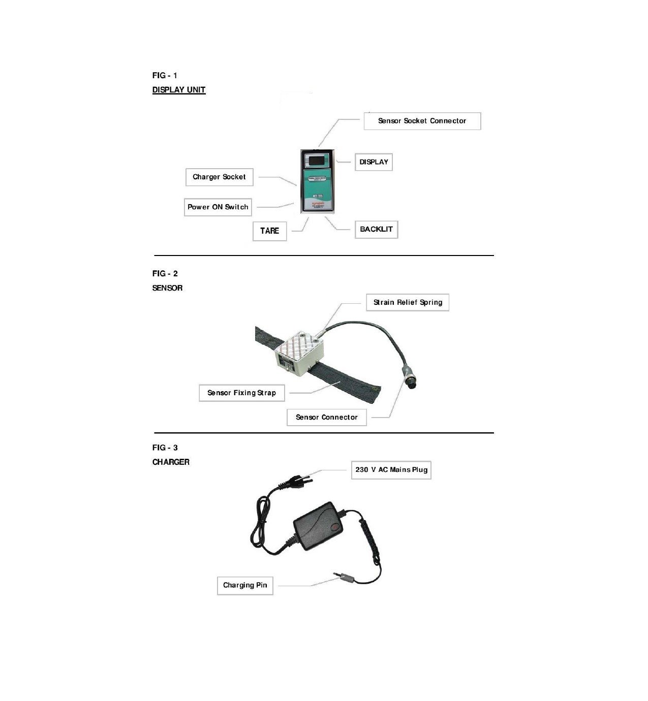
3.0 Keyboard Description
The front Panel of the Instrument Consists of 2 Keys Whose Description is given
3.1 TARE
Key is used for ZERO the any value at no load condition. In the normal mode, this Key is also used for resetting the Peak value.
3.2 BACKLIT
BACKLIT Key is used for illumination of BACKLIT.
4.0 Instrument Setup:
Connect the input sensor to the Bayonet connector with its respective mating plug; the connections are as shown below:
- ✅ Pin 1 - RED
- ✅ Pin 2 - BLACK
- ✅ Pin 3 - GREEN
- ✅ Pin 4 - WHITE
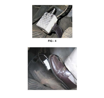
4.0 Installing the Sensor
- ✅ Place the sensor properly on the clutch.
- ✅ Fix it using the strap provided.
- ✅ Apply force using your foot.
- ✅ Observe the reading on the display.
6.0 Sequence Of Operation :
- 6.1 Before the Pedal Force Meter can be used, the battery inside the Display unit has to be charged. Insert charges pin to the charger socket. Switch off the power ON switch on the display unit (Ref Fig - 3 & Fig 1). Apply 230 V Mains to the charger. Keep the system for charging for 8 to 10 hours for full charging. However it can be intermittently charged & used in case of emergencies.
- 6.2 Disconnect the charger; connect the load cell end connector to the display unit (Ref Fig 2 & Fig 1). Strap the load cell to the Pedal (Fig 4). Switch on the display unit by power on switch. Before applying force, Tare the reading to zero by pressing Tare on the display unit.
- 6.3 Apply pedal force on the load cell (Fig - 5) and note down the reading. If you want to take repeat reading press Tare to make it zero & apply pedal force. The unit can be used till low battery indication appears on the display. To take readings in the dark, press backlit which will enable the display light. To turn of the light once again press backlit ((Ref Sl. No. 3.1 & 3.2).
5.0 Do's and Don'ts
✅ Do's
- ✔ Keep the Display unit for charging when not in use.
- ✔ Store the Pedal Force Kit in a cool & dry place when not in use.
❌ Don'ts
- ❌ Don't keep the display unit powered ON when not in use.
- ❌ Don't splash water to clean the display unit & the load cell.
- ❌ Don't pull the cable or exert pressure on the cable.
- ❌ Don't apply force more than the specified capacity (100 Kgs).
- ❌ Don't expose the display unit to high temperature (more than 45° C) & load cell to more than 55° C.
- ❌ Don't exert too much force while plugging the connectors or operating the switch.